
Writing Your Own Toy OS [writed by Krishnakumar R. , Raghu and Chitkala ]
Writing Your Own Toy OS (Part I)
By Krishnakumar R.
<!-- END header -->This article is a hands-on tutorial for building a small boot sector. The first section provides the theory behind what happens at the time the computer is switched on. It also explains our plan. The second section tells all the things you should have on hand before proceeding further, and the third section deals with the programs. Our little startup program won't actually boot Linux, but it will display something on the screen.
1. Background
1.1 The Fancy Dress
The microprocessor controls the computer. At startup, every microprocessor is just another 8086. Even though you may have a brand new Pentium, it will only have the capabilities of an 8086. From this point, we can use some software and switch processor to the infamous protected mode . Only then can we utilize the processor's full power.
1.2 Our Role
Initially, control is in the hands of the BIOS. This is nothing but a collection of programs that are stored in ROM. BIOS performs the POST (Power On Self Test). This checks the integrity of the computer (whether the peripherals are working properly, whether the keyboard is connected, etc.). This is when you hear those beeps from the computer. If everything is okay, BIOS selects a boot device. It copies the first sector (boot sector) from the device, to address location 0x7C00. The control is then transferred to this location. The boot device may be a floppy disk, CD-ROM, hard disk or some device of your choice. Here we will take the boot device to be a floppy disk. If we had written some code into the boot sector of the floppy, our code would be executed now. Our role is clear: just write some programs to the boot sector of the floppy.
1.3 The Plan
First write a small program in 8086 assembly (don't be frightened; I will teach you how to write it), and copy it to the boot sector of the floppy. To copy, we will code a C program. Boot the computer with that floppy, and then enjoy.
2. Things You Should Have
This is an assembler. The assembly code we write is converted to an object file by this tool.
This is the linker. The object code generated by as86 is converted to actual machine language code by this tool. Machine language will be in a form that 8086 understands.
The C compiler. For now we need to write a C program to transfer our OS to the floppy.
A floppy will be used to store our operating system. This also is our boot device.
You know what this is for.
3. 1, 2, 3, Start!
3.1 The Boot Sector
Grab your favourite editor and type in these few lines.
entry start
start:
      mov ax,#0xb800
      mov es,ax
      seg es
      mov [0],#0x41
      seg es
      mov [1],#0x1f
loop1: jmp loop1
This is an assembly language that as86 will understand. The first statement specifies the entry point where the control should enter the program. We are stating that control should initially go to label start. The 2nd line depicts the location of the label start (don't forget to put ":" after the start). The first statement that will be executed in this program is the statement just after start.
0xb800 is the address of the video memory. The # is for representing an immediate value. After the execution of
mov ax,#0xb800
es register. es stands for the extra segment register. Remember that 8086 has a segmented architecture. It has segments like code segments, data segments, extra segments, etc.--hence the segment registers cs, ds, es. Actually, we have made the video memory our extra segment, so anything written to extra segment would go to video memory.
To display any character on the screen, you need to write two bytes to the video memory. The first is the ascii value you are going to display. The second is the attribute of the character. Attribute has to do with which colour should be used as the foreground, which for the background, should the char blink and so on. seg es is actually a prefix that tells which instruction is to be executed next with reference to es segment. So, we move value 0x41, which is the ascii value of character A, into the first byte of the video memory. Next we need to move the attribute of the character to the next byte. Here we enter 0x1f, which is the value for representing a white character on a blue background. So if we execute this program, we get a white A on a blue background. Finally, there is the loop. We need to stop the execution after the display of the character, or we have a loop that loops forever. Save the file as boot.s.
The idea of video memory may not be very clear, so let me explain further. Suppose we assume the screen consists of 80 columns and 25 rows. So for each line we need 160 bytes, one for each character and one for each character's attribute. If we need to write some character to column 3 then we need to skip bytes 0 and 1 as they is for the 1st column; 2 and 3 as they are for the 2nd column; and then write our ascii value to the 4th byte and its attribute to the 5th location in the video memory.
3.2 Writing Boot Sector to Floppy
We have to write a C program that copies our code (OS code) to first sector of the floppy disk. Here it is:
#include <sys/types.h> /* unistd.h needs this */
#include <unistd.h>    /* contains read/write */
#include <fcntl.h>

int main()
{
        char boot_buf[512];
        int floppy_desc, file_desc;


        file_desc = open("./boot", O_RDONLY);
        read(file_desc, boot_buf, 510);
        close(file_desc);

        boot_buf[510] = 0x55;
        boot_buf[511] = 0xaa;

        floppy_desc = open("/dev/fd0", O_RDWR);
        lseek(floppy_desc, 0, SEEK_CUR);
        write(floppy_desc, boot_buf, 512);
        close(floppy_desc);
}
First, we open the file boot in read-only mode, and copy the file descripter of the opened file to variable file_desc. Read from the file 510 characters or until the file ends. Here the code is small, so the latter case occurs. Be decent; close the file.
The last four lines of code open the floppy disk device (which mostly would be /dev/fd0). It brings the head to the beginning of the file using lseek, then writes the 512 bytes from the buffer to floppy.
The man pages of read, write, open and lseek (refer to man 2) would give you enough information on what the other parameters of those functions are and how to use them. There are two lines in between, which may be slightly mysterious. The lines:
boot_buf[510] = 0x55;
boot_buf[511] = 0xaa;
boot to a buffer named boot_buf. It makes the required changes to 510th and 511th bytes and then writes boot_buf to floppy disk. If we execute the code, the first 512 bytes of the floppy disk will contain our boot code. Save the file as write.c.
3.3 Let's Do It All
To make executables out of this file you need to type the following at the Linux bash prompt.
as86 boot.s -o boot.o

ld86 -d boot.o -o boot

cc write.c -o write
First, we assemble the boot.s to form an object file boot.o. Then we link this file to get the final file boot. The -d for ld86 is for removing all headers and producing pure binary. Reading man pages for as86 and ld86 will clear any doubts. We then compile the C program to form an executable named write.
Insert a blank floppy into the floppy drive and type
./write
Then you will see an 'A' (with white foreground color on a blue background). That means that the system has booted from the boot floppy we have made and then executed the boot sector program we wrote. It is now in the infinite loop we had written at the end of our boot sector. We must now reboot the computer and remove the our boot floppy to boot into Linux.
From here, we'll want to insert more code into our boot sector program, to make it do more complex things (like using BIOS interrupts, protected-mode switching, etc). The later parts (PART II, PART III etc. ) of this article will guide you on further improvements. Till then GOOD BYE ! <!-- *** BEGIN bio *** -->
 Krishnakumar R.
Krishnakumar is a final year B.Tech student at Govt. Engg. College Thrissur, Kerala, India. His journey into the land of Operating systems started with module programming in linux . He has built a routing operating system by name GROS.(Details available at his home page: www.askus.way.to ) His other interests include Networking, Device drivers, Compiler Porting and Embedded systems.
Writing Your Own Toy OS (PART II)
By Krishnakumar R.
<!-- END header -->Part I was published in April.
The next thing that any one should know after learning to make a boot sector and before switching to protected mode is, how to use the BIOS interrupts. BIOS interrupts are the low level routines provided by the BIOS to make the work of the Operating System creator easy. This part of the article would deal with BIOS interrupts.
1. Theory
1.1 Why BIOS ?
BIOS does the copying of the boot sector to the RAM and execution of code there. Besides this there are lot of things that the BIOS does. When an operating system boots up it does not have a video driver or a floppy driver or any other driver as such. To include any such driver in the boot sector is next to impossible. So some other way should be there. The BIOS comes to our help here. BIOS contains various routines we can use. For example there are ready made routines available for various purposes like, checking the equipments installed, controlling the printer, finding out memory size etc. These routines are what we call BIOS interrupts.
1.2 How do we invoke BIOS interrupts ?
In ordinary programming languages we invoke a routine by making a call to the routine. For example in a C program, if there is a routine by name display having parameters noofchar - number of characters to be displayed, attr - attribute of characters displayed is to just to call the routine that is just write the name of the routine. Here we make use of interrupts. That is we make use of assembly instruction int.
For example for printing something on the screen we call the C function like this :
display(noofchar, attr);
Equivalent to this, when we use BIOS, we write :
int 0x10
1.3 Now, how do we pass the parameters ?
Before calling the BIOS interrupt, we need to load certain values in prespecified format in the registers. Suppose we are using BIOS interrupt 13h, which is for transferring the data from the floppy to the memory. Before calling interrupt 13h we have to specify the segment address to which the data would be copied. Also we need to pass as parameters the drive number, track number, sector number, number of sectors to be transferred etc. This we do by loading the prespecified registers with the needed values. The idea will be clear after you read the explanation on the boot sector we are going to construct.
One important thing is that the same interrupt can be used for a variety of purposes. The purpose for which a particular interrupt is used depends upon the function number selected. The choice of the function is made depending on the value present in the ah register. For example interrupt 13h can be used for displaying a string as well as for getting the cursor position. If we move value 3 to register ah then the function number 3 is selected which is the function used for getting the cursor position. For displaying the string we move 13h to register ah which corresponds to displaying a string on screen.
2. What are we going to do ?
This time our source code consists of two assembly language programs and one C program. First assembly file is the boot sector code. In the boot sector we have written the code to copy the second sector of the floppy to the memory segment 0x500 ( the address location is 0x5000). This we do using BIOS interrupt 13h. The code in the boot sector then transfers control to offset 0 of segment 0x500. The code in the second assembly file is for displaying a message on screen using BIOS interrupt 10h. The C program is for transferring the executable code produced from assembly file 1 to boot sector and the executable code produced from the assembly file 2 to the second sector of the floppy.
3. The boot sector
Using interrupt 13h, the boot sector loads the second sector of the floppy into memory location 0x5000 (segment address 0x500). Given below is the source code used for this purpose. Save the code to file bsect.s.
LOC1=0x500

entry start
start:
        mov ax,#LOC1
        mov es,ax
        mov bx,#0

        mov dl,#0
        mov dh,#0
        mov ch,#0
        mov cl,#2
        mov al,#1

        mov ah,#2

        int 0x13

        jmpi 0,#LOC1
The first line is similar to a macro. The next two statements might be familiar to you by now. Then we load the value 0x500 into the es register. This is the address location to which the code in the second sector of the floppy (the first sector is the boot sector) is moved to. Now we specify the offset within the segment as zero.
Next we load drive number into dl register, head number into dh register, track number into ch register, sector number into cl register and the number of sectors to be transferred to registeral. So we are going to load the sector 2, of track number 0, drive number 0 to segment 0x500. All this corresponds to 1.44Mb floppy.
Moving value 2 into register ah is corresponds to choosing a function number. This is to choose from the functions provided by the interrupt 13h. We choose function number 2 which is the function used for transferring data from floppy.
Now we call interrupt 13h and finally jump to 0th offset in the segment 0x500.
4. The second sector
The code in the second sector will as given below :
entry start
start:
        mov     ah,#0x03
        xor     bh,bh
        int     0x10

        mov     cx,#26
        mov     bx,#0x0007
        mov     bp,#mymsg
        mov     ax,#0x1301
        int     0x10

loop1:  jmp     loop1

mymsg:
        .byte  13,10
        .ascii "Handling BIOS interrupts"
This code will be loaded to segment 0x500 and executed. The code here uses interrupt 10h to get the current cursor position and then to print a message.
The first three lines of code (starting from the 3rd line) are used to get the current cursor position. Here function number 3 of interrupt 13h is selected. Then we clear the value in bh register. We move the number of characters in the string to register ch. To bx we move the page number and the attribute that is to be set while displaying. Here we are planning to display white characters on black background. Then address of the message to be be printed in moved to register bp. The message consists of two bytes having values 13 and 10 which correspond to an enter which is the Carriage Return (CR) and the Line Feed (LF) together. Then there is a 24 character string. Then we select the function which corresponds to printing the string and then moving the cursor. Then comes the call to interrupt. At the end comes the usual loop.
5. The C program
The source code of the C program is given below. Save it into file write.c.
#include <sys/types.h> /* unistd.h needs this */
#include <unistd.h>    /* contains read/write */
#include <fcntl.h>

int main()
{
                char boot_buf[512];
                int floppy_desc, file_desc;

                file_desc = open("./bsect", O_RDONLY);

                read(file_desc, boot_buf, 510);
                close(file_desc);

                boot_buf[510] = 0x55;
                boot_buf[511] = 0xaa;

                floppy_desc = open("/dev/fd0", O_RDWR);

                lseek(floppy_desc, 0, SEEK_SET);
                write(floppy_desc, boot_buf, 512);

                file_desc = open("./sect2", O_RDONLY);
                read(file_desc, boot_buf, 512);
                close(file_desc);

                lseek(floppy_desc, 512, SEEK_SET);
                write(floppy_desc, boot_buf, 512);

                close(floppy_desc);
}
In PART I of this article I had given the description about making the boot floppy. Here there are slight differences. We first copy the file bsect, the executable code produced from bsect.s to the boot sector. Then we copy the sect2 the executable corresponding to sect2.s the second sector of the floppy. Also the changes to be made to make the floppy bootable have also been performed.
6. Downloads
You can download the sources from
Remove the txt extension of the files, and type
make
at the shell prompt or you can compile everything separately. Type
as86 bsect.s -o bsect.o

ld86 -d bsect.o -o bsect
and repeat the same for sect2.s giving sect2. Compile write.c and execute it after putting the boot floppy in to drive by typing :
cc write.c -o write
./write
7. What Next?
After booting with the floppy you can see the string being displayed. Thus we will have used the BIOS interrupts. In the next part of this series I hope to write about how we can switch the processor to protected mode. Till then, bye ! <!-- *** BEGIN bio *** --><spacer type="vertical" size="30"></spacer>
Krishnakumar R.
Krishnakumar is a final year B.Tech student at Govt. Engg. College Thrissur, Kerala, India. His journey into the land of Operating systems started with module programming in linux . He has built a routing operating system by name GROS.(Details available at his home page: www.askus.way.to ) His other interests include Networking, Device drivers, Compiler Porting and Embedded systems.
|
Writing your own Toy OS - Part III By Raghu and Chitkala |
<!-- END header -->
[Krishnakumar is unable to continue this series himself due to other commitments, so he has handed it over to his junior colleagues, Raghu and Chitkala, who have written part III. -Editor.]
In Parts I and II of this series, we examined the process of using tools available with Linux to build a simple boot sector and access the system BIOS. Our toy OS will be closely modelled after a `historic' Linux kernel - so we have to switch to protected mode real soon! This part shows you how it can be done.
1. What is Protected Mode ?
The 80386+ provides many new features to overcome the deficiencies of 8086 which has almost no support for memory protection, virtual memory, multitasking, or memory above 640K - and still remain compatible with the 8086 family. The 386 has all the features of the 8086 and 286, with many more enhancements. As in the earlier processors, there is the real mode. Like the 286, the 386 can operate in protected mode. However, the protected mode on 386 is vastly different internally. Protected mode on the 386 offers the programmer better protection and more memory than on the 286. The purpose of protected mode is not to protect your program. The purpose is to protect everyone else (including the operating system) from your program.
1.1 Protected Mode vs Real Mode
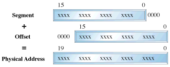
Superficially protected mode and real mode don't seem to be very different. Both use memeory segmentation, interrupts and device drivers to handle the hardware. But there are differences which justify the existence of two separate modes. In real mode, we can view memory as 64k segments atleast 16bytes apart. Segmentation is handled through the use of an internal mechanism in conjunction with segment registers. The contents of these segment registers (CS,DS,SS...) form part of the physical address that the CPU places on the addresss bus. The physical address is generated by multiplying the segment register by 16 and then adding a 16 bit offset. It is this 16 bit offset that limits us to 64k segments.
fig 1 : Real Mode Addressing
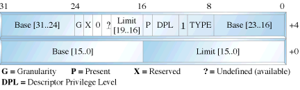
In protected mode, segmentation is defined via a set of tables called descriptor tables. The segment registers contain pointers into these tables. There are two types of tables used to define memory segmentation : The Global Descriptor Table and The Local Descriptor Table. The GDT contains the basic descriptors that all applications can access. In real mode one segment is 64k big followed by the next in a 16 byte distance. In protected mode we can have a segment as big as 4Gb and we can put it wherever we want. The LDT contains segmentation information specific to a task or program. An OS for instance could set up a GDT with its system descriptors and for each task an LDT with appropriate descriptors. Each descriptor is 8 bytes long. The format is given below (fig 3). Each time a segment register is loaded, the base address is fetched from the appropriate table entry. The contents of the descriptor is stored in a programmer invisible register called shadow registers so that future references to the same segment can use this information instead of referencing the table each time. The physical address is formed by adding the 16 or 32 bit offset to the base address in the shadow register.These differences are made clear in figures 1 and 2.
fig 2 : Protected Mode Addressing
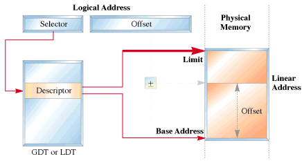
fig 3 : Segment Descriptor Format
We have yet another table called the interrupt descriptor table or the IDT. The IDT contains the interrupt descriptors. These are used to tell the processor where to find the interrupt handlers. It contains one entry per interrupt, just like in Real Mode, but the format of these entries is totally different. We are not using the IDT in our code to switch to the protected mode so further details are not given.
2. Entering Protected Mode
The 386 has four 32 bit control registers named CR0, CR1, CR2 and CR3. CR1 is reserved for future processors, and is undefined for the 386. CR0 contains bits that enable and disable paging and protection and bits that control the operation of the floating point coprocessor. CR2 and CR3 are used by the paging mechanism. We are concerned with bit 0 of the CR0 register or the PE bit or the protection enable bit. When PE = 1, the processor is said to be operating in protected mode with the segmentation mechanism we described earlier. If PE = 0, the processor operates in real mode. The 386 also has the segmentation table base registers like GDTR, LDTR and IDTR.These registers address segments that contain the descriptor tables. The GDTR points to the GDT. The 48 bit GDTR defines the base and the limit of the GDT directly with a 32 bit linear address and a 16 bit limit.
Switching to protected mode essentially implies that we set the PE bit. But there are a few other things that we must do. The program must initialise the system segments and control registers. Immediately after setting the PE bit to 1 we have to execute a jump instruction to flush the execution pipeline of any instructions that may have been fetched in the real mode. This jump is typically to the next instruction. The steps to switch to protected mode then reduces to the following :
- Build the GDT.
- Enable protected mode by setting the PE bit in CR0.
- Jump to clear the prefetch queue.
We'll now give the code to perform this switching.
3. What we need
- a blank floppy
- NASM assembler
Click here to download the code. Type in the code to a file by name abc.asm. Assemble it by typing the command nasm abc.asm. This will produce a file called abc. Then insert the floppy and type the following command dd if=abc of=/dev/fd0. This command will write the file abc to the first sector of the floppy. Then reboot the system. You should see the following sequence of messages.
- Our os booting........................
- A (Brown colour)
- Switching to protected mode....
- A (White colour)
4. The Code that does everything !
We'll first give the code to perform the switching. It is followed by a detailed explanation.
As mentioned in the previous article (Part 1) the BIOS selects the boot device and places the first sector into the address 0x7c00. We thus start writung our code at 0x7c00.This is what is implied by the org directive.
FUNCTIONS USED
print_mesg: This routine uses the subfunction 13h of BIOS interrupt 10h to write a string to the screen.The attributes are specified by placing appropriate values in various registers. Interrupt 10h is used for various string manipulations.We store the subfn number 13h in ah which specifies that we wish to print a string. Bit 0 of the al register determines the next cursor position;if it is 0 we return to the beginning of the next line after the function call, if it is 1 the cursor is placed immediately following the last character printed.
The video memory is split into several pages called video display pages.Only one page can be displayed at a time(For further details on video memory refer Part 1).The contents of bh indicates the page number,bl specifies the colour of the character to be printed. cx holds the length of the string to be printed.Register dx specifies the cursor position. Once all the attributes have been initialised we call BIOS interrupt 10h.
get_key: We use BIOS interrupt 16h whose sub function 00h is used to get the next character from the screen. Register ah holds the subfn number.
clrscr: This function uses yet another subfn of int 10h i.e 06h to clear the screen before printing a string.To indicate this we initialise al to 0.Registers cx and dx specify the window size to be cleared;in this case it is the entire screen. Register bh indicates the colour with which the screen has to be filled;in this case it is black.
Where everything begins !!
The first assembly language statement is a short jump to the begin_boot code.We intend to print a brown 'A'in real-mode,set up a GDT,switch to protected mode and print a white 'A'.Both these modes use their own addressing methods.
In Real-Mode :
We use segment register gs to point to video memory.We use a CGA adapter(default base address 0xb8000).But hey we have a missing 0 in the code.Well the Real-mode segmentation unit provides the additional 0.This is a matter of convenience,as the 8086 usually does a 20bit address manipulation.This has been carried over in the real-mode addressing of the 386.The ascii value for A is 0x41;0x06 specifies that we need a brown coloured character.The display stays till we press a key.Next let us display a message on the screen saying we are going to the world of protected mode.So let us point the bp(base pointer register to the message to be printed).
Launchpad to the protected mode :
We don't need any interrupts bothering us,while in protected mode do we ?So lets disable them(interrupts that is).That is what cli does. We will enable them later.So lets start by setting up the GDT.We initialise 4 descriptors in our attempt to switch to protected mode. These descriptors initialise our code segment(code_gdt), data and stack segments (data_gdt) and the video segment in order to access the video memory. A dummy descriptor is also initialised although it's never used except if you want to triple fault of course. This is a null descriptor. Let us probe into some of the segment descriptor fields.
- The first word holds the limit of the segment, which for simplicity is assigned the maximum of FFFF(4G). For the video segment we set a predefined value of 3999 (80 cols * 25 rows * 2bytes - 1).
- The base address of the code and data segments is set to 0x0000. For the video segment it is 0xb8000 (Video Memory base address).
The GDT base address has to be loaded into GDTR system register. The gdtr segment is loaded with the size of the GDT in the first word and the base address in the next dword. The lgdt instruction then loads the gdt segment into the GDTR register.Now we are ready to actually switch to pmode. We start by setting the least significant bit of CR0 to 1( ie the PE bit).We are not yet in full protected mode!
Section 10.3 of the INTEL 80386 PROGRAMMER'S REFERENCE MANUAL 1986 states : Immediately after setting the PE flag,the initialization code must flush the processor's instruction prefetch queue by executing a JMP instruction.The 80386 fetches and decodes instructions and addresses before they are used; however, after a change into protected mode, the prefetched instruction information (which pertains to real-address mode) is no longer valid. A JMP forces the processor to discard the invalid information.
We are in protected mode now. Want to check it out? Let's get our A printed in white. For this we initialise the data and extra segments with the data segment selector (datasel). Initialise gs with the video segment selector (videosel). To display a white 'A' move a word containing the ascii value and attribute to location [gs:0000] ie b8000 : 0000. The spin loop preserves the text on the screen until the system is rebooted.
The times instruction is used to fill in 0s in the remaining unused bytes of the sector.To indicate that this is a bootable sector we write AA55 in bytes 511,512. That's about all.
<!-- *** BEGIN bio *** -->
Raghu and Chitkala
Raghu and Chitkala are seventh-semester students at the Government Engineering College, Thrissur, India. Their final-year project is porting User Mode Linux to BSD. Their interests include Operating Systems, Networking and Microcontrollers. <!-- *** END bio *** --><!-- *** BEGIN copyright *** -->
Copyright © 2002, Raghu and Chitkala. Copying license http://www.linuxgazette.net/copying.html
Published in Issue 82 of Linux Gazette, September 2002
附录:
org 0x07c00 ; Start address 0000:7c00
jmp short begin_boot ; Jump to start of boot routine & skip other data
bootmesg db "Our OS boot sector loading ......"
pm_mesg db "Switching to protected mode ...."
dw 512 ; Bytes per sector
db 1 ; Sectors per cluster
dw 1 ; Number of reserved sectors
db 2 ; Number of FATs
dw 0x00e0 ; Number of dirs in root
dw 0x0b40 ; Number of sectors in volume
db 0x0f0 ; Media descriptor
dw 9 ; Number of sectors per FAT
dw 18 ; Number of sectors per track
dw 2 ; Number of read/write sectors
dw 0 ; Number of hidden sectors
print_mesg :
mov ah,0x13 ; Fn 13h of int 10h writes a whole string on screen
mov al,0x00 ; bit 0 determines cursor pos,0->point to start after ; function call,1->point to last position written
mov bx,0x0007 ; bh -> screen page ie 0,bl = 07 ie white on black
mov cx,0x20 ; Length of string here 32
mov dx,0x0000 ; dh->start cursor row,dl->start cursor column
int 0x10 ; call bios interrupt 10h
ret ; Return to calling routine
get_key :
mov ah,0x00
int 0x16 ; Get_key Fn 00h of 16h,read next character
ret
clrscr :
mov ax,0x0600 ; Fn 06 of int 10h,scroll window up,if al = 0 clrscr
mov cx,0x0000 ; Clear window from 0,0
mov dx,0x174f ; to 23,79
mov bh,0 ; fill with colour 0
int 0x10 ; call bios interrupt 10h
ret
begin_boot :
call clrscr ; Clear the screen first
mov bp,bootmesg ; Set the string ptr to message location
call print_mesg ; Print the message
call get_key ; Wait till a key is pressed
bits 16
call clrscr ; Clear the screen
mov ax,0xb800 ; Load gs to point to video memory
mov gs,ax ; We intend to display a brown A in real mode
mov word [gs:0],0x641 ; display
call get_key ; Get_key again,ie display till key is pressed
mov bp,pm_mesg ; Set string pointer
call print_mesg ; Call print_mesg subroutine
call get_key ; Wait till key is pressed
call clrscr ; Clear the screen
cli ; Clear or disable interrupts
lgdt[gdtr] ; Load GDT
mov eax,cr0 ; The lsb of cr0 is the protected mode bit
or al,0x01 ; Set protected mode bit
mov cr0,eax ; Mov modified word to the control register
jmp codesel:go_pm
bits 32
go_pm :
mov ax,datasel
mov ds,ax ; Initialise ds & es to data segment
mov es,ax
mov ax,videosel ; Initialise gs to video memory
mov gs,ax
mov word [gs:0],0x741 ; Display white A in protected mode
spin : jmp spin ; Loop
bits 16
gdtr :
dw gdt_end-gdt-1 ; Length of the gdt
dd gdt ; physical address of gdt
gdt
nullsel equ $-gdt ; $->current location,so nullsel = 0h
gdt0 ; Null descriptor,as per convention gdt0 is 0
dd 0 ; Each gdt entry is 8 bytes, so at 08h it is CS
dd 0 ; In all the segment descriptor is 64 bits
codesel equ $-gdt ; This is 8h,ie 2nd descriptor in gdt
code_gdt ; Code descriptor 4Gb flat segment at 0000:0000h
dw 0x0ffff ; Limit 4Gb bits 0-15 of segment descriptor
dw 0x0000 ; Base 0h bits 16-31 of segment descriptor (sd)
db 0x00 ; Base addr of seg 16-23 of 32bit addr,32-39 of sd
db 0x09a ; P,DPL(2),S,TYPE(3),A->Present bit 1,Descriptor ; privilege level 0-3,Segment descriptor 1 ie code ; or data seg descriptor,Type of seg,Accessed bit
db 0x0cf ; Upper 4 bits G,D,0,AVL ->1 segment len is page ; granular, 1 default operation size is 32bit seg ; AVL : Available field for user or OS
; Lower nibble bits 16-19 of segment limit
db 0x00 ; Base addr of seg 24-31 of 32bit addr,56-63 of sd
datasel equ $-gdt ; ie 10h, beginning of next 8 bytes for data sd
data_gdt ; Data descriptor 4Gb flat seg at 0000:0000h
dw 0x0ffff ; Limit 4Gb
dw 0x0000 ; Base 0000:0000h
db 0x00 ; Descriptor format same as above
db 0x092
db 0x0cf
db 0x00
videosel equ $-gdt ; ie 18h,next gdt entry
dw 3999 ; Limit 80*25*2-1
dw 0x8000 ; Base 0xb8000
db 0x0b
db 0x92 ; present,ring 0,data,expand-up,writable
db 0x00 ; byte granularity 16 bit
db 0x00
gdt_end
times 510-($-$$) db 0 ; Fill bytes from present loc to 510 with 0s
dw 0x0aa55 ; Write aa55 in bytes 511,512 to indicate that ; it is a bootable sector.
bsect.s文件如下:
LOC1=0x500
entry start
start:
mov ax,#LOC1
mov es,ax
mov bx,#0 ;segment offset
mov dl,#0 ;drive no.
mov dh,#0 ;head no.
mov ch,#0 ;track no.
mov cl,#2 ;sector no.( 1..18 )
mov al,#1 ;no. of sectors tranferred
mov ah,#2 ;function no.
int 0x13
jmpi 0,#LOC1
sect2.s文件如下:
entry start
start:
mov ah,#0x03 ; read cursor position.
xor bh,bh
int 0x10
mov cx,#26; length of our beautiful string.
mov bx,#0x0007 ; page 0, attribute 7 (normal)
mov bp,#mymsg
mov ax,#0x1301 ; write string, move cursor
int 0x10
loop1:jmploop1
mymsg:
.byte 13,10
.ascii "Handling BIOS interrupts"
write.c文件如下:
#include <sys/types.h> /* unistd.h needs this */
#include <unistd.h> /* contains read/write */
#include <fcntl.h>
int main()
{
char boot_buf[512];
int floppy_desc, file_desc;
file_desc = open("./bsect", O_RDONLY);
read(file_desc, boot_buf, 510);
close(file_desc);
boot_buf[510] = 0x55;
boot_buf[511] = 0xaa;
floppy_desc = open("/dev/fd0", O_RDWR);
lseek(floppy_desc, 0, SEEK_SET);
write(floppy_desc, boot_buf, 512);
file_desc = open("./sect2", O_RDONLY);
read(file_desc, boot_buf, 512);
close(file_desc);
lseek(floppy_desc, 512, SEEK_SET);
write(floppy_desc, boot_buf, 512);
close(floppy_desc);
}
Makefile文件如下:
all : bsect sect2 write
bsect: bsect.o
ld86 -d bsect.o -o bsect
sect2 : sect2.o
ld86 -d sect2.o -o sect2
bsect.o : bsect.s
as86 bsect.s -o bsect.o
sect2.o : sect2.s
as86 sect2.s -o sect2.o
write : write.c
cc write.c -o write
clean :
rm bsect.o sect2.o bsect sect2 write
<!-- *** END bio *** --><!-- *** BEGIN copyright *** --><!-- *** END bio *** --><!-- *** BEGIN copyright *** -->code.asm文件如下:


发表评论

相关推荐
我学着用matlab编写的用来解最优化问题的fabonacci程序
This is a SNMP Test Program. This code is the simplest. This code is writed by C Language.
A very useful book to introduce system thinking,writed by Barry M. Richmond
Converter C++ to Java. Very useful for combination modules which are writed on different language.
用QT库版本4编写的IRC聊天室。
the webservice writed with C#. FB4 call WEBSERVICE,base on SOAP protocol.. the webservice writed with C#. FB4 call WEBSERVICE,base on SOAP protocol.. the webservice writed with C#. FB4 call ...
使用labview通过串口读取和写入三菱FX PLC的D寄存器的例子,可作为学习和参考。
Media Player is a plugin for eclipse writed by java. Now it can only play audio, and play video will come soon. 0.0.2 (20030617) 1. Support mouse right click. 2. You can refresh the play ...
A error concealment sorce code that writed by myself.It s psnr not as good as JM86,but it s good in edge information.Help someone can improve it and it can do something for those strugling for ...
source is writed by verilog about I2C. it s not perpectly.^^
It is a 4 bit s mul writed by VHDL language which is improved.
使用 C# 编写的AEC文件加密核心代码源码。
%writed by CapRogers. %Welcome to use getbode. %It's a function helping you to get bode chart without inputing any parameter but only a formula. %This .m file can only use 's' as variate. %attention:...
mimikatz is a tool I've made to learn C and make somes experiments with Windows security. It's now well known to extract plaintexts passwords, hash, PIN code and kerberos tickets from memory. ...
Codes writed by a geek woring in Red Hat China.
DW8051 is designed by synopsys, and its instruction cycle is 4 clock, which lead to about 3 times faster than Intel 8051 with the same oscillator frequency. I writed ram, rom, some other perpherals ...
A paper writed by Michael Bailey,Evan Cook,Farnam Jahanian,Yunjing Xu University of Michigan
Codes writed by a geek woring in Red Hat China.
one simple method used in computation,it is usefull writed by myself
256B ecc(writed by c++)